The Bypass TAP (also called the bypass switch) provides fail-safe access ports for embedded active security devices such as IPS and next-generation firewalls (NGFWS). The bypass switch is deployed between network devices and in front of network security tools to provide a reliable point of isolation between the network and the security layer. They bring full support to networks and security tools to avoid the risk of network outages.
Solution 1 1 Link Bypass Network Tap(Bypass Switch) - Independent
Application:
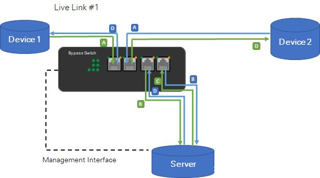
The Bypass Network Tap(Bypass Switch) connects to the two network devices through Link ports and connects to a third-party server through Device ports.
The trigger of the Bypass Network Tap(Bypass Switch) is set to Ping, which sends successive Ping requests to the server. Once the server stops responding to pings, the Bypass Network Tap(Bypass Switch) enters bypass mode.
When the server starts responding again, the Bypass Network Tap(Bypass Switch) switches back to throughput mode.
This application can only work through ICMP(Ping). No heartbeat packets are used to monitor the connection between the server and the Bypass Network Tap(Bypass Switch).
Solution 2 Network Packet Broker + Bypass Network Tap(Bypass Switch)
Network Packet Broker(NPB) + Bypass Network Tap(Bypass Switch) -- Normal status
Application:
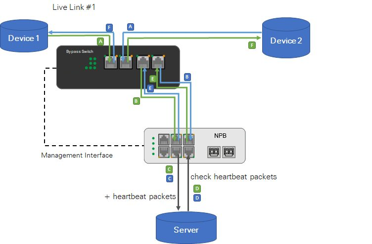
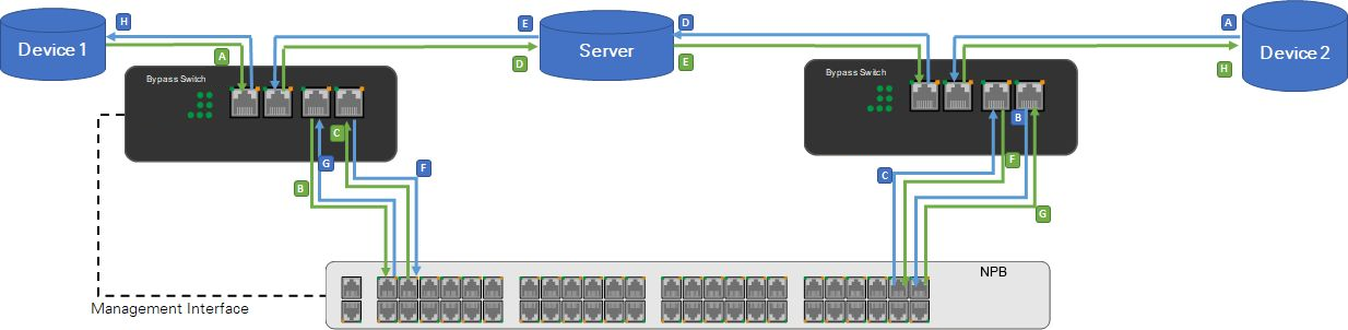
The Bypass Network Tap(Bypass Switch) connects to two network devices through Link ports and to Network Packet Broker(NPB) through Device ports. The third-party server connects to Network Packet Broker(NPB) using 2 x 1G copper cables. Network Packet Broker(NPB) sends heartbeat packets to the server through port #1 and wants to receive them again on port #2.
The trigger for the Bypass Network Tap(Bypass Switch) is set to REST, and Network Packet Broker(NPB) runs the bypass application.
Traffic in throughput mode:
Device 1 ↔ Bypass Switch/Tap ↔ NPB ↔ Server ↔ NPB ↔ Bypass Switch/Tap ↔ Device 2
Network Packet Broker(NPB) + Bypass Network Tap(Bypass Switch) -- Software Bypass
Software Bypass description:
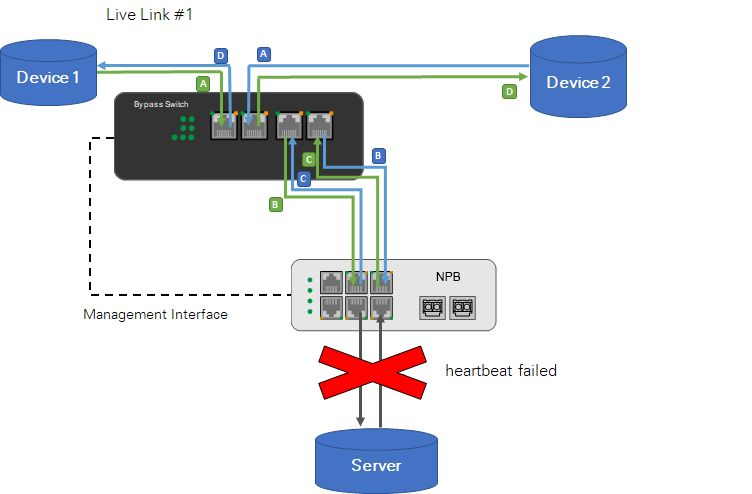
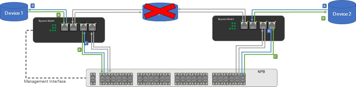
If Network Packet Broker(NPB) does not detect heartbeat packets, it will enable software bypass.
The configuration of Network Packet Broker(NPB) is automatically changed to send incoming traffic back to the Bypass Network Tap(Bypass Switch), thereby reinserting the traffic into the live link with minimal packet loss.
The Bypass Network Tap(Bypass Switch) does not need to respond at all because all bypasses are done by Network Packet Broker(NPB).
Traffic in Software Bypass:
Device 1 ↔ Bypass Switch/Tap ↔ NPB ↔ Bypass Switch/Tap ↔ Device 2
Network Packet Broker(NPB) + Bypass Network Tap(Bypass Switch) -- Hardware bypass
Hardware Bypass description:
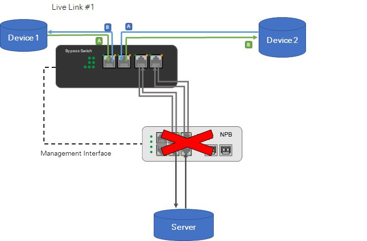
In the event that Network Packet Broker(NPB) fails or the connection between the Network Packet Broker(NPB) and Bypass Network Tap(Bypass Switch) is disconnected, the Bypass Network Tap(Bypass Switch) switches to bypass mode to keep the real-time link working.
When the Bypass Network Tap(Bypass Switch) goes into bypass mode, Network Packet Broker(NPB) and the external server are bypassed and do not receive any traffic until the Bypass Network Tap(Bypass Switch) switches back to throughput mode.
The bypass mode is triggered when the Bypass Network Tap(Bypass Switch) is no longer connected to the power supply.
Hardware off-line traffic:
Device 1 ↔ Bypass Switch/Tap ↔ Device 2
Solution 3 Two Bypass Network Taps(Bypass Switches) for each link
Configuration instructions:
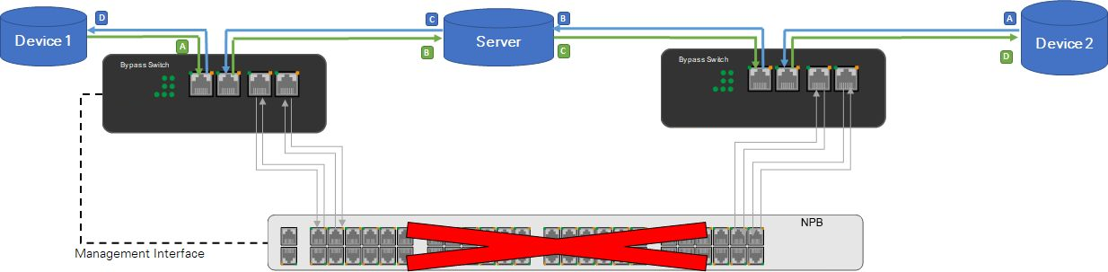
In this setup, 1 copper link of 2 devices connected to a known server is bypassed by two Bypass Network Taps(Bypass Switches). The advantage of this over the 1 bypass solution is that when the network packet broker(NPB) connection is disrupted, the server is still part of the live link.
2 * Bypass Network Taps(Bypass Switches) per link - Software Bypass
Software Bypass description:
If Network Packet Broker(NPB) does not detect heartbeat packets, it will enable software bypass. The Bypass Network Tap(Bypass Switch) does not need to react at all because all bypasses are done by Network Packet Broker(NPB).
Traffic in software bypass:
Device 1 ↔ Bypass Switch/Tap 1 ↔ Network Packet Broker(NPB) ↔ Bypass Switch/Tap 2 ↔ Device 2
2 * Bypass Network Taps(Bypass Switches) per link - Hardware Bypass
Hardware Bypass description:
In the event that the Network Packet Broker(NPB) fails or the connection between the Bypass Network Tap(Bypass Switch) and the Network Packet Broker(NPB) is disconnected, both Bypass Network Taps(Bypass Switches) are switched to bypass mode to maintain the active link.
In contrast to the "1 Bypass per link" setting, the server is still included in the live link.
Hardware off-line traffic:
Device 1 ↔ Bypass Switch/Tap 1 ↔Server ↔ Bypass Switch/Tap 2 ↔ Device 2
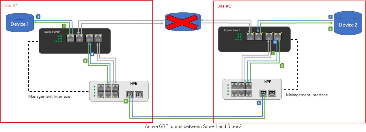
Solution 4 Two Bypass Network Taps(Bypass Switches) are configured for each link on the two sites
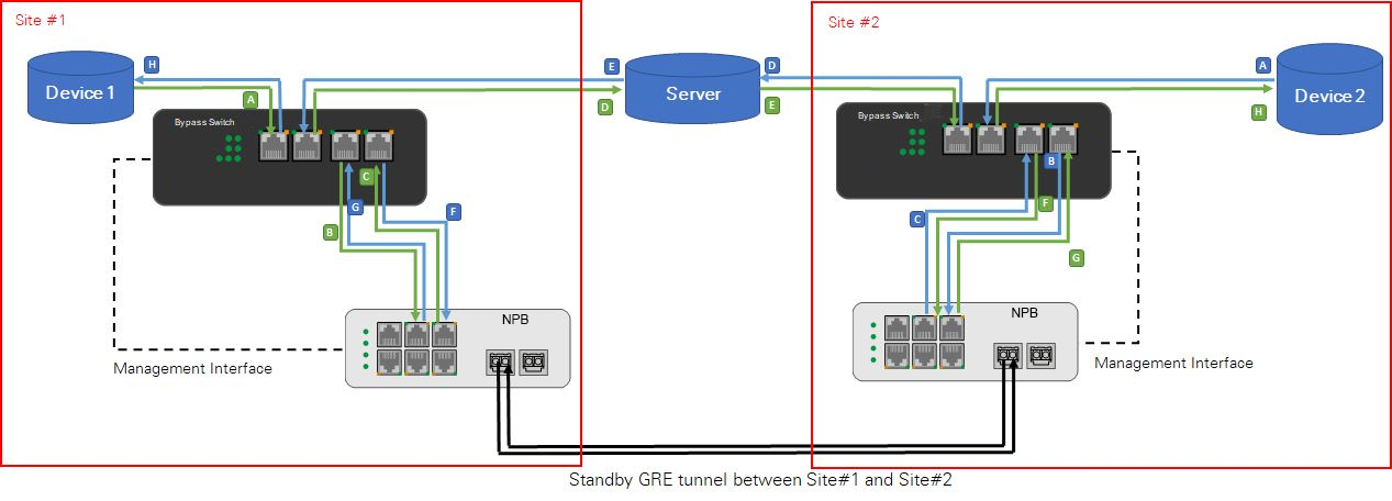
Setting instructions:
Optional: Two Network Packet Brokers(NPBs) can be used to connect two different sites over the GRE tunnel instead of one Network Packet Broker(NPB). In the event that the server connecting the two sites fails, it will bypass the server and the traffic which can be distributed through the GRE tunnel of Network Packet Broker(NPB) (as shown in Figures below).
Post time: Mar-06-2023


