In order to meet the needs of cloud services, the network is gradually divided into Underlay and Overlay. The Underlay network is the physical equipment such as routing and switching in the traditional data center, which still believes in the concept of stability and provides reliable network data transmission capabilities. Overlay is the business network encapsulated on it, closer to the service, through the VXLAN or GRE protocol encapsulation, to provide users with an easy to use network services. Underlay network and Ooverlay network are related and decoupled, and they are related to each other and can evolve independently.
The Underlay network is the foundation of the network. If the underlay network is unstable, there is no SLA for the business. After the three-layer network architecture and Fat-Tree network architecture, the data center network architecture is transitioning to the Spine-Leaf architecture, which ushered in the third application of the CLOS network model.
Traditional Data center Network architecture
Three Layer Design
From 2004 to 2007, the three-tier network architecture was very popular in data centers. It has three layers: the core layer (the high-speed switching backbone of the network), the aggregation layer (which provides policy-based connectivity), and the access layer (which connects workstations to the network).The model is as follows:
Three-layer Network Architecture
Core Layer: The core switches provide high-speed forwarding of packets in and out of the data center, connectivity to the multiple aggregation layers, and a resilient L3 routing network that typically serves the entire network.
Aggregation Layer: The aggregation switch connects to the access switch and provides other services, such as firewall, SSL offload, intrusion detection, network analysis, etc.
Access Layer: The access switches are usually at the Top of the Rack, so they are also called ToR (Top of Rack) switches, and they physically connect to the servers.
Typically, the aggregation switch is the demarcation point between L2 and L3 networks: the L2 network is below the aggregation switch, and the L3 network is above. Each group Of aggregation switches manages a Point Of Delivery (POD), and each POD is an independent VLAN network.
Network Loop and Spanning Tree protocol
The formation of loops is mostly caused by confusion caused by unclear destination paths. When users build networks, in order to ensure reliability, they usually use redundant devices and redundant links, so that loops are inevitably formed. The layer 2 network is in the same broadcast domain, and the broadcast packets will be transmitted repeatedly in the loop, forming a broadcast storm, which can cause port blockage and equipment paralysis in an instant. Therefore, in order to prevent broadcast storms, it is necessary to prevent the formation of loops.
To prevent the formation of loops and to ensure reliability, it is only possible to turn redundant devices and redundant links into backup devices and backup links. That is, redundant device ports and links are blocked under normal circumstances and do not participate in the forwarding of data packets. Only when the current forwarding device, port, link failure, resulting in network congestion, redundant device ports and links will be opened, so that the network can be restored to normal. This automatic control is implemented by the Spanning Tree Protocol (STP).
The spanning tree protocol operates between the access layer and the sink layer, and at its core is a spanning tree algorithm running on each STP-enabled bridge, which is specifically designed to avoid bridging loops in the presence of redundant paths. STP selects the best data path for forwarding messages and disallows those links that are not part of the spanning tree, leaving only one active path between any two network nodes and the other uplink will be blocked.
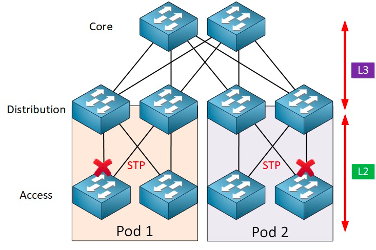
STP has many benefits: it is simple, plug-and-play, and requires very little configuration. The machines within each pod belong to the same VLAN, so the server can migrate the location arbitrarily within the pod without modifying the IP address and gateway.
However, parallel forwarding paths cannot be used by STP, which will always disable redundant paths within the VLAN. Disadvantages of STP:
1. Slow convergence of topology. When the network topology changes, the spanning tree protocol takes 50-52 seconds to complete the topology convergence.
2, can not provide the function of load balancing. When there is a loop in the network, the spanning tree protocol can only simply Block the loop, so that the link can not forward data packets, wasting network resources.
Virtualization and East-West Traffic Challenges
After 2010, in order to improve the utilization of computing and storage resources, data centers began to adopt virtualization technology, and a large number of virtual machines began to appear in the network. Virtual technology transforms a server into multiple logical servers, each VM can run independently, has its own OS, APP, its own independent MAC address and IP address, and they connect to the external entity through the virtual switch (vSwitch) inside the server.
Virtualization has a companion requirement: live migration of virtual machines, the ability to move a system of virtual machines from one physical server to another while maintaining the normal operation of services on the virtual machines. This process is insensitive to end users, administrators can flexibly allocate server resources, or repair and upgrade physical servers without affecting the normal use of users.
In order to ensure that the service is not interrupted during the migration, it is required that not only the IP address of the virtual machine is unchanged, but also the running state of the virtual machine (such as the TCP session state) must be maintained during the migration, so the dynamic migration of the virtual machine can only be carried out in the same layer 2 domain, but not across the layer 2 domain migration. This creates the need for larger L2 domains from the access layer to the core layer.
The dividing point between L2 and L3 in the traditional large layer 2 network architecture is at the core switch, and the data center below the core switch is a complete broadcast domain, that is, the L2 network. In this way, it can realize the arbitrariness of device deployment and location migration, and it does not need to modify the configuration of IP and gateway. The different L2 networks (VLans) are routed through the core switches. However, the core switch under this architecture needs to maintain a huge MAC and ARP table, which puts forward high requirements for the ability of the core switch. In addition, the Access Switch (TOR) also limits the scale of the whole network. These eventually limit the scale of the network, network expansion and elastic ability, the delay problem across the three layers of scheduling, can not meet the needs of future business.
On the other hand, the east-west traffic brought by virtualization technology also brings challenges to the traditional three-layer network. Data center traffic can be broadly divided into the following categories:
North-south traffic: Traffic between clients outside the data center and the data center server, or traffic from the data center server to the Internet.
East-west traffic: Traffic between servers within a data center, as well as traffic between different data centers, such as disaster recovery between data centers, communication between private and public clouds.
The introduction of virtualization technology makes the deployment of applications more and more distributed, and the "side effect" is that the east-west traffic is increasing.
Traditional three-tier architectures are typically designed for North-South traffic. While it can be used for east-west traffic, it may ultimately fail to perform as required.
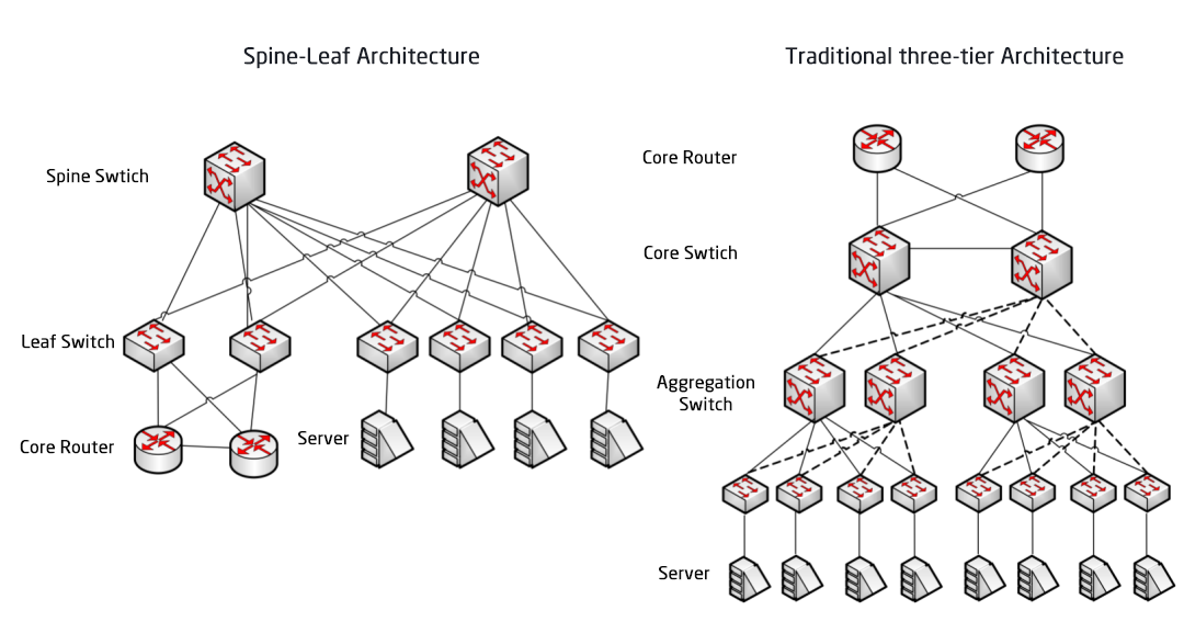
Traditional three-tier architecture vs. Spine-Leaf architecture
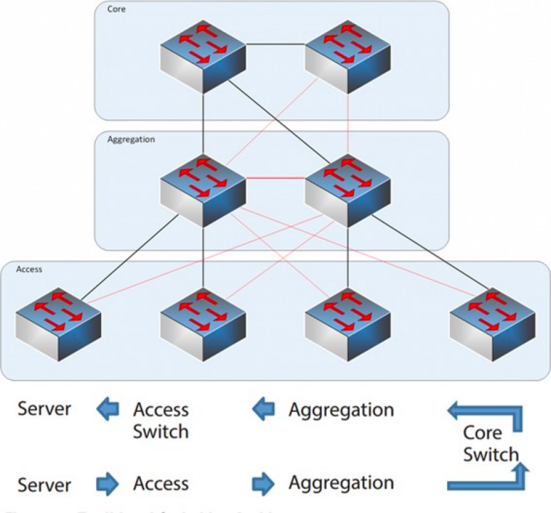
In a three-tier architecture, east-west traffic must be forwarded through devices in the aggregation and core layers. Unnecessarily passing through many nodes. (Server -> Access -> Aggregation -> Core Switch -> Aggregation -> Access Switch -> Server)
Therefore, if a large amount of east-west traffic is run through a traditional three-tier network architecture, devices connected to the same switch port may compete for bandwidth, resulting in poor response times obtained by end users.
Disadvantages of traditional three-layer network architecture
It can be seen that the traditional three-layer network architecture has many shortcomings:
Bandwidth waste: To prevent looping, STP protocol is usually run between the aggregation layer and the access layer, so that only one uplink of the access switch really carries traffic, and the other uplinks will be blocked, resulting in a waste of bandwidth.
Difficulty in large-scale network placement: With the expansion of network scale, data centers are distributed in different geographical locations, virtual machines must be created and migrated anywhere, and their network attributes such as IP addresses and gateways remain unchanged, which requires the support of fat Layer 2. In the traditional structure, no migration can be performed.
Lack of East-West traffic: The three-tier network architecture is mainly designed for North-South traffic, although it also supports east-west traffic, but the shortcomings are obvious. When the east-west traffic is large, the pressure on the aggregation layer and core layer switches will be greatly increased, and the network size and performance will be limited to the aggregation layer and core layer.
This makes enterprises fall into the dilemma of cost and scalability: supporting large-scale high-performance networks requires a large number of convergence layer and core layer equipment, which not only brings high costs to enterprises, but also requires that the network must be planned in advance when building the network. When the network scale is small, it will cause a waste of resources, and when the network scale continues to expand, it is difficult to expand.
The Spine-Leaf Network Architecture
What is the Spine-Leaf network architecture?
In response to the above problems, a new data center design, Spine-Leaf network architecture, has emerged, which is what we call leaf ridge network.
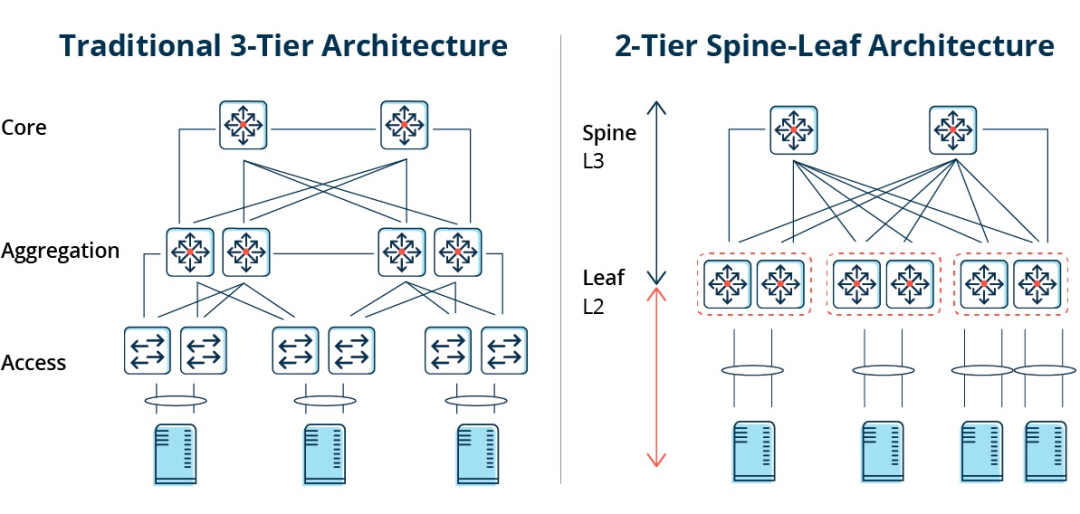
As the name suggests, the architecture has a Spine layer and a Leaf layer, including spine switches and leaf switches.
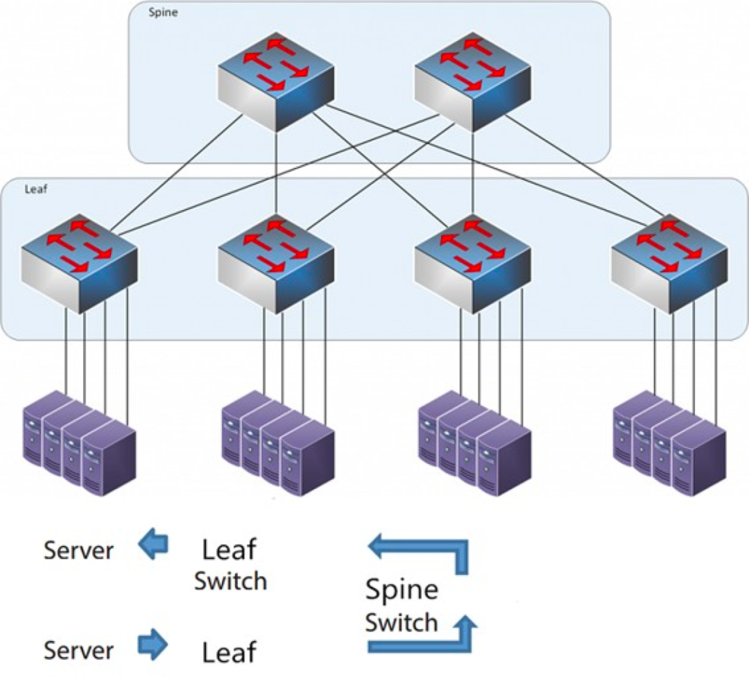
The Spine-Leaf Architecture
Each leaf switch is connected to all the ridge switches, which are not directly connected to each other, forming a full-mesh topology.
In spine-and-leaf, a connection from one Server to another passes through the same number of devices (Server -> Leaf -> Spine Switch -> Leaf Switch -> Server), which ensures predictable latency. Because a packet only needs to go through one spine and another leaf to reach the destination.
How Spine-Leaf works?
Leaf Switch: It is equivalent to the access switch in the traditional three-tier architecture and directly connects to the physical server as the TOR (Top Of Rack). The difference with the access switch is that the demarcation point of the L2/L3 network is now on the Leaf switch. The Leaf switch is above the 3-layer network, and the Leaf switch is below the independent L2 broadcast domain, which solves the BUM problem of the large 2-layer network. If two Leaf servers need to communicate, they need to use L3 routing and forward it through a Spine switch.
Spine Switch: Equivalent to a core switch. ECMP (Equal Cost Multi Path) is used to dynamically select multiple paths between the Spine and Leaf switches. The difference is that the Spine now simply provides a resilient L3 routing network for the Leaf switch, so the data center's north-south traffic can be routed from the Spine switch instead of directly. North-south traffic can be routed from the edge switch parallel to the Leaf switch to the WAN router.
Comparison between Spine/Leaf network architecture and traditional three-layer network architecture
Advantages of Spine-Leaf
Flat: A flat design shortens the communication path between servers, resulting in lower latency, which can significantly improve application and service performance.
Good scalability: when the bandwidth is insufficient, increasing the number of ridge switches can horizontally extend the bandwidth. When the number of servers increases, we can add leaf switches if the port density is insufficient.
Cost reduction: Northbound and southbound traffic, either exiting from leaf nodes or exiting from ridge nodes. East-west flow, distributed over multiple paths. In this way, the leaf ridge network can use fixed configuration switches without the need for expensive modular switches, and then reduce the cost.
Low Latency and Congestion Avoidance: Data flows in a Leaf ridge network have the same number of hops across the network regardless of source and destination, and any two servers are Leaf - >Spine - >Leaf three-hop reachable from each other. This establishes a more direct traffic path, which improves performance and reduces bottlenecks.
High Security and Availability: The STP protocol is used in the traditional three-tier network architecture, and when a device fails, it will reconverge, affecting the network performance or even failure. In the leaf-ridge architecture, when a device fails, there is no need to reconverge, and the traffic continues to pass through other normal paths. The network connectivity is not affected, and the bandwidth is only reduced by one path, with little performance impact.
Load balancing via ECMP is well suited for environments where centralized network management platforms such as SDN are used. SDN allows to simplify the configuration, management and re-routing of traffic in the event of blockage or link failure, making the intelligent load balancing full mesh topology a relatively simple way to configure and manage.
However, the Spine-Leaf architecture has some limitations:
One disadvantage is that the number of switches increases the size of the network. The data center of leaf ridge network architecture needs to increase switches and network equipment proportionally to the number of clients. As the number of hosts increases, a large number of leaf switches are needed to uplink to the ridge switch.
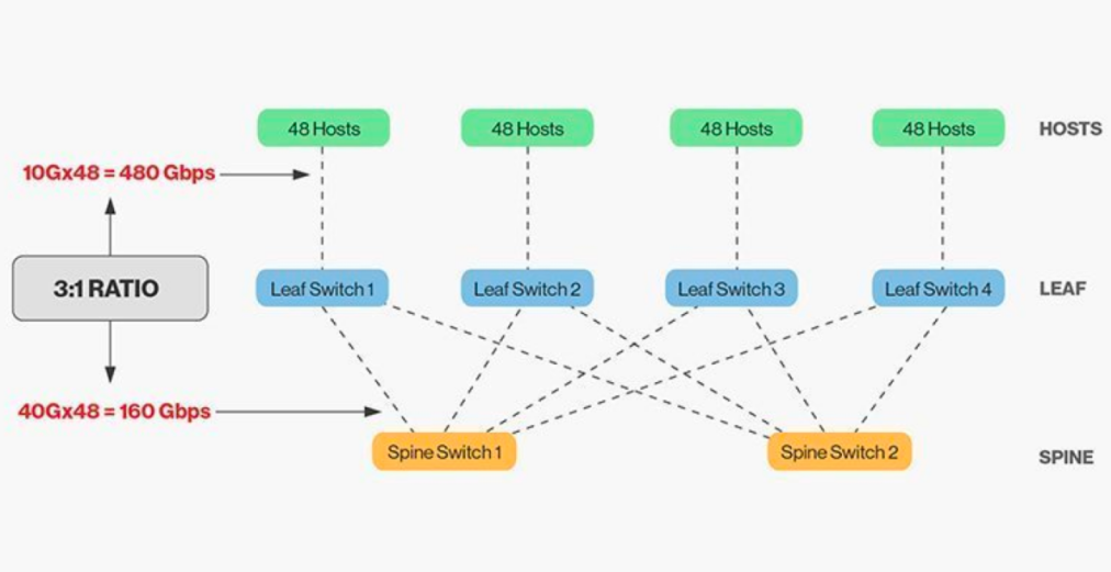
The direct interconnection of ridge and leaf switches requires matching, and in general, the reasonable bandwidth ratio between leaf and ridge switches cannot exceed 3:1.
For example, there are 48 10Gbps rate clients on the leaf switch with a total port capacity of 480Gb/s. If the four 40G uplink ports of each leaf switch are connected to the 40G ridge switch, it will have an uplink capacity of 160Gb/s. The ratio is 480:160, or 3:1. Data center uplinks are typically 40G or 100G and can be migrated over time from a starting point of 40G (Nx 40G) to 100G (Nx 100G). It is important to note that the uplink should always run faster than the downlink so as not to block the port link.
Spine-Leaf networks also have clear wiring requirements. Because each leaf node must be connected to each spine switch, we need to lay more copper or fiber optic cables. The distance of the interconnect drives up the cost. Depending on the distance between the interconnected switches, the number of high-end optical modules required by the Spine-Leaf architecture is tens of times higher than that of the traditional three-tier architecture, which increases the overall deployment cost. However, this has led to the growth of the optical module market, especially for high speed optical modules such as 100G and 400G.
Post time: Jan-26-2026


