As enterprise network architecture evolves toward high-speed fiber backbone deployment, full-spectrum visibility of in-band network traffic has become a non-negotiable foundation of robust network security, performance troubleshooting, and regulatory compliance monitoring. Passive Network Tap technology, specifically inline FBT-based fiber passive taps, delivers lossless, non-intrusive Network Traffic Capture without introducing latency, network downtime, or attack surfaces into production infrastructure. This comprehensive technical guide dissects core operating principles of Mylinking™ Passive Tap FBT Optical Splitter inline fiber tap solutions, elaborates on real-world inline deployment topology matching the provided Inline Fiber Tap Solution schematic, benchmarks passive tap performance against SPAN port mirroring and active tapping alternatives, details vertical industry implementation scenarios for network monitoring and cybersecurity defense, and outlines customizable product specifications tailored to modern multi-gigabit fiber networking environments. IT infrastructure engineers, SOC cybersecurity analysts, NOC operation managers, and network compliance officers will gain actionable insights to select, deploy, and optimize passive fiber tap hardware to solve critical network observability pain points, strengthen end-to-end network security posture, and streamline full-packet network traffic capture across hybrid on-premises and cloud-connected fiber networks.
1. Introduction: The Modern Demand for Reliable Passive Network Tap in Enterprise Network Monitoring & Cybersecurity
Global enterprise fiber networking bandwidth continues exponential annual growth, driven by cloud migration, SD-WAN deployment, rising encrypted business traffic, remote workforce expansion, and evolving advanced persistent threat (APT) cyberattack vectors targeting core network perimeters. Traditional network visibility methodologies, predominantly dependent on switch SPAN/RSPAN port mirroring, suffer inherent limitations including egress packet drop during high traffic congestion, constrained monitoring bandwidth ceiling, excessive CPU resource consumption on production switches, and incomplete Network Traffic Capture of asymmetric bidirectional fiber flows—creating critical blind spots that directly compromise enterprise Network Security Visibility and comprehensive Network Monitoring capabilities.
According to 2025 global cybersecurity infrastructure research data, over 62% of enterprise security breaches originated from unmonitored perimeter backbone fiber links where incomplete traffic capture prevented early detection of lateral threat movement and data exfiltration activity. Against this industry-wide visibility gap, Passive Network Tap emerges as the most trusted, cost-effective physical-layer access solution to copy full bidirectional network packets traversing fiber cabling without modifying original live data transmission. Mylinking™, a specialized global manufacturer of fiber optic passive splitters and inline network tapping hardware, engineered its flagship Passive Tap FBT Optical Splitter series purpose-built for inline fiber deployment, precisely aligning with the inline topology illustrated in the official Inline Fiber Tap Solution architecture diagram, to deliver zero-impact full-packet capture for next-generation enterprise network security and monitoring workflows.
This article centers on core SEO target keywords: Passive Network Tap, Network Traffic Capture, Network Security, Network Monitoring, contextualizing technical product details alongside real-world deployment value to address the most pressing visibility challenges facing modern IT and cybersecurity teams worldwide. From core perimeter router-firewall interconnection links to access-layer switch downlink fiber trunks, inline passive fiber taps embed transparent observability into existing network architecture without requiring production network reconfiguration or scheduled maintenance downtime, cementing passive tapping as the gold-standard physical access method for compliant, threat-focused network monitoring.
2. Core Definition & Operating Principle of Passive Network Tap: What Is Inline FBT Fiber Passive Tap?
2.1 Formal Definition of Passive Network Tap
A Passive Network Tap (Test Access Point) is a fully passive, non-powered physical-layer fiber component engineered to split inbound/outbound optical signals passing through inline fiber cabling, separating the primary working signal toward its original destination while diverting a pre-defined fixed percentage of replicated optical traffic toward dedicated monitoring hardware for Network Traffic Capture and subsequent analysis. Distinct from active powered tapping devices or switch-based SPAN mirroring, passive taps contain no active electronic chipsets, require zero external power supply to operate, feature no assignable IP/MAC addresses or remote management interfaces, and cannot be compromised or exploited by external threat actors—an irreplaceable design benefit for high-priority Network Security monitoring deployments.
Inline passive fiber taps are installed physically in-series (inline) along existing live fiber links, which differentiates them from parallel off-tap passive splitters deployed on spare switch ports; inline placement ensures every single packet crossing the monitored fiber trunk undergoes complete duplication for monitoring, eliminating packet loss risks common to alternative visibility approaches.
2.2 FBT Optical Splitter Core Working Mechanism for Mylinking Passive Tap
Mylinking’s Passive Tap leverages proven FBT (Fused Biconical Taper) optical coupling manufacturing technology as the foundational core of its inline passive tap hardware, built via proprietary high-precision fiber fusion and tapering production processes detailed on the official product landing page (https://www.mylinking.com/mylinking-passive-tap-fbt-optical-splitter-product/)
(1) Two precisely matched single-mode/multimode bare optical fibers are fused together at a designated coupling region under controlled high-temperature thermal processing; gradual mechanical stretching forms a tapered evanescent-wave coupling window where transmitted optical signal energy partially bleeds across adjacent fiber cores via optical near-field coupling effect.
(2) Pre-calibrated production parameters (fusion temperature, draw tension, coupling length) rigidly control fixed splitting ratios — Mylinking standard configurable split options include industry-preferred 70/30, 80/20, 90/10 (primary network transmission/monitoring tap output), alongside custom-specified splitting ratios for specialized low-loss network monitoring requirements.
(3) Primary majority optical power (e.g.,70% under 70:30 configuration) continues unaltered along the original inline fiber path to preserve end-to-end production network connectivity, while the remaining minority signal percentage (e.g.,30%) is routed to dedicated MON (monitor) port outputs on the passive tap chassis to feed replicated traffic to network analysis appliances for full Network Traffic Capture and deep-packet inspection.
(4) The entire FBT core assembly is sealed within rugged rack-mountable metal chassis compliant with standard 1U/2U 19-inch rack specifications, supporting broad operating temperature range (-40°C ~ +85°C) for deployment across harsh server room, telecom POP, and outdoor cabinet environments with minimal environmental sensitivity.
Unlike PLC-based passive splitters optimized for uniform multi-port signal distribution, FBT design excels in bidirectional inline fiber tapping thanks to superior bidirectional signal symmetry, lower polarization-dependent loss (PDL), and flexible single-link split customization—core reasons Mylinking selects FBT construction for its flagship inline Passive Network Tap product lineup focused exclusively on network monitoring and security traffic capture use cases.
3. Inline Fiber Tap Deployment Topology Breakdown (Based on Official Mylinking Inline Solution Diagram)
The provided Inline Fiber Tap Solution schematic visually documents canonical inline deployment architecture of Mylinking Passive Network Tap between enterprise core firewall downlink fiber and access-layer uplink switch fiber trunk, segmented into four core functional network zones detailed below, directly mapping blue production fiber cabling and orange monitoring tap cabling notation from the technical diagram:
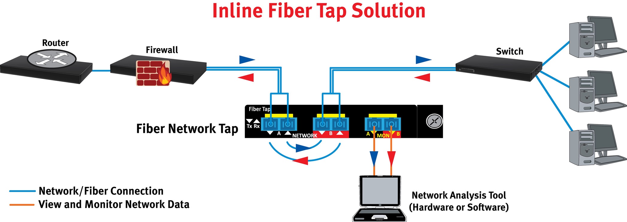
3.1 Zone 1: Core Perimeter Network Segment (Router → Firewall Inbound/Outbound Backbone Link)
The upstream network segment originates at enterprise edge Router, which establishes wide-area internet/MPLS connectivity before terminating fiber into the organization’s perimeter Firewall appliance—the critical security chokepoint for all inbound external internet traffic and outbound internal user internet-bound data. All cross-perimeter traffic (bidirectional, denoted via red/blue directional traffic arrows in the diagram) passes entirely through the subsequent inline fiber tap device post-firewall egress, making this interconnection link the highest-value monitoring anchor point for perimeter threat detection and outbound data leakage prevention via full Network Traffic Capture.
3.2 Zone 2: Mylinking Inline Passive Fiber Tap Core Deployment Point (Inline Serial Insertion on Live Firewall-Switch Fiber Trunk)
The Passive Network Tap chassis is physically inserted inline into the continuous fiber run originating from Firewall output port and terminating into core access Switch input port, breaking the original single fiber patch cord into two discrete fiber segments (Firewall → Tap NETWORK A port; Tap NETWORK B port → Access Switch). Key port functional definition from the schematic:
○ NETWORK A / NETWORK B Ports: Bidirectional production fiber pass-through interfaces; 100% of primary network optical signal passes transparently between A and B ports to maintain uninterrupted live production connectivity, zero circuit downtime required during tap hot-installation for most field deployments.
○ MON A / MON B Monitoring Output Ports: Dedicated tap replication ports hardwired to the internal FBT split core, sourcing split replicated bidirectional traffic (inbound Firewall → Switch via MON A, outbound Switch → Firewall via MON B) via orange monitoring fiber cabling toward downstream network analysis hardware as shown in the illustration.
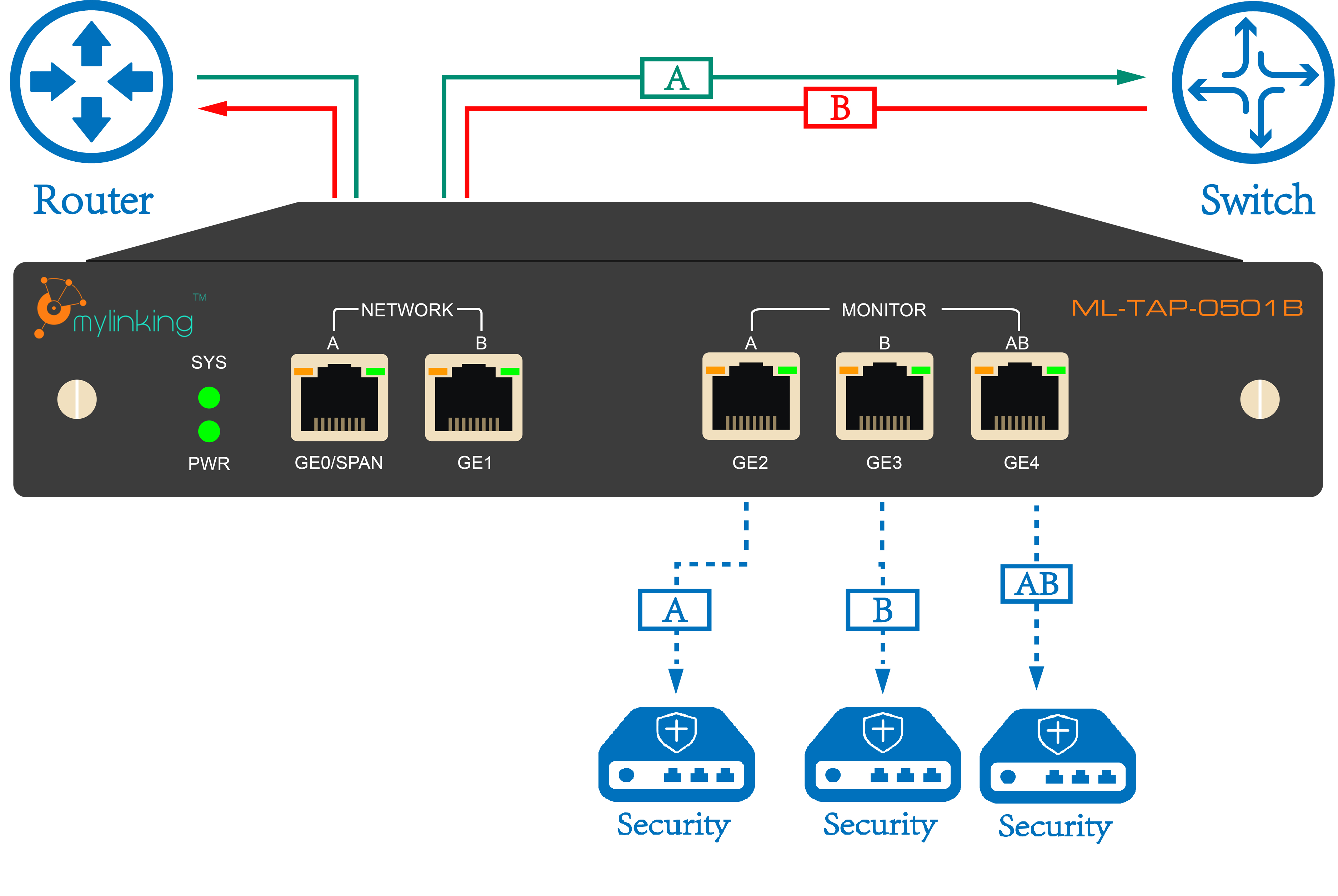
Multiple independent inline tap port banks are integrated within a single rack-mount Mylinking passive tap chassis (visible as three separate dual-port tap modules in the reference drawing), enabling simultaneous inline tapping of multiple discrete fiber trunks within one compact rack unit for consolidated multi-link network monitoring—eliminating scattered standalone tap device sprawl in dense data center rack deployments.
3.3 Zone3: Downstream Access Switch & End-User Terminal Infrastructure
Post-tap NETWORK B fiber connects directly into core layer access Switch uplink port; the switch further distributes downlink connectivity to on-premises end-user desktop/workstation endpoints as visualized on the right side of the topology. By tapping the pre-switch core trunk rather than individual switch downlink ports, IT teams capture aggregated end-to-end north-south user internet traffic in a single monitoring feed, drastically simplifying centralized Network Monitoring of all internal-to-external organizational communication flows without deploying discrete tap hardware per user access port.
3.4 Zone4: Off-Band Network Analysis Tool Receiving Replicated Tap Traffic
Orange MON-port fiber cabling from the passive tap’s dedicated monitoring outputs runs to standalone Network Analysis Tool hardware (laptop/physical packet capture appliance/IDS/IPS/NDR cybersecurity platform as labeled in the diagram). This complete physical air-gap separation between production network path and isolated monitoring analysis environment stands among passive tap’s most impactful Network Security advantages: compromise of the downstream analysis tool cannot propagate lateral cyberattacks back into the live production network, as passive tap’s one-way optical split design prohibits reverse signal injection from monitoring ports into core production fiber links. Captured full packet data is processed locally by analysis software/hardware for threat hunting, forensic packet logging, performance bottleneck troubleshooting, and regulatory compliance traffic auditing.
4. Passive Network Tap vs SPAN Port Mirror vs Active Tap: Head-to-Head Technical & Security Comparison for Network Traffic Capture
To quantify unique value proposition of Mylinking FBT Passive Network Tap for enterprise Network Traffic Capture, we benchmark three mainstream network visibility solutions across core technical, security, deployment, and cost parameters—core comparison data heavily referenced for SEO content addressing common user search intent of “SPAN vs TAP for network monitoring”:
| Evaluation Parameter | Mylinking Passive Network Tap (FBT Inline Fiber Tap) | Switch SPAN/RSPAN Port Mirroring | Powered Active Network Tap |
| Power Dependency | Fully passive, zero external power required; production link remains live permanently regardless of tap hardware status | Relies entirely on live switch CPU power; SPAN functionality fails upon switch resource exhaustion | Requires continuous AC/DC power supply; power outage triggers link bypass or full circuit interruption depending on model |
| Packet Capture Integrity | Zero packet loss under line-rate full bandwidth load; FBT physical split copies every transmitted bit with 100% capture fidelity | Severe packet drops during switch CPU/port buffer congestion (common above 70% port bandwidth utilization); asymmetric bidirectional flows frequently incomplete | Near-zero packet loss under rated bandwidth but introduces microsecond-level electrical latency to inline production traffic |
| Network Security Exposure | No electronics/IP/MAC addresses; non-exploitable passive component, zero attack surface for cyber threat actors | Switch CPU exposed to monitoring traffic abuse; malicious actors can manipulate SPAN configuration to disable visibility or intercept mirrored data | Active onboard firmware creates potential exploit surface; remote management ports introduce additional network attack vectors |
| Live Production Impact | Transparent inline insertion, no production bandwidth/CPU overhead added to live network infrastructure | Consumes substantial switch internal CPU and memory resources; high-volume mirroring degrades native switch forwarding performance | Inline electrical processing adds measurable latency to production packet forwarding |
| Bidirectional Capture Capability | Natively splits both ingress/egress optical signals simultaneously via separate MON A/B outputs for complete bidirectional traffic logging | Many legacy switches limit SPAN to single-direction mirroring; RSPAN further introduces intermediate packet replication loss across transit switches | Supports full bidirectional capture at cost of inline traffic latency |
| Total Ownership Cost (TCO) | Mid-range upfront hardware cost, negligible long-term maintenance; zero recurring power/software licensing fees | Zero upfront hardware cost but hidden operational expense from switch performance degradation and troubleshooting labor | Highest total cost: premium hardware price plus continuous power consumption and annual firmware maintenance/licensing |
Key Takeaway for SEO & Technical Guidance: For mission-critical perimeter Network Security monitoring and lossless full-spectrum Network Traffic Capture, Passive Network Tap consistently outperforms SPAN mirror and active tapping alternatives—especially for high-speed 1G/10G/25G/100G fiber backbone links where packet loss from SPAN creates unacceptable security and compliance blind spots, justifying industry-wide shift toward inline passive fiber tap deployment in regulated financial, government, and healthcare verticals.
5. Key Technical Advantages of Mylinking™ FBT Passive Tap for Network Security & Full-Spectrum Network Monitoring
Built upon refined FBT optical splitting manufacturing with decades of fiber component engineering experience, Mylinking’s flagship Passive Network Tap FBT Optical Splitter integrates multiple differentiated technical benefits tailored explicitly to enterprise-grade Network Monitoring and cybersecurity-focused Network Traffic Capture, core selling points optimized for SEO conversion targeting IT procurement and security decision-makers:
5.1 Zero Attack Surface Maximizes Core Network Security Posture
As a fully passive all-optical component with no embedded microprocessors, operating firmware, or network-assignable addressing schemes, Mylinking passive tap hardware cannot be remotely accessed, compromised, or weaponized by malicious hackers to infiltrate production network infrastructure—an essential feature for SOC teams securing high-value regulated environments (banking, federal government, critical infrastructure). The physical one-way optical split between production NETWORK ports and isolated MON monitoring ports creates inherent optical air gap isolation; no electrical or optical signal can travel backward from monitoring appliances into live production fiber, eliminating lateral threat propagation risks originating from compromised IDS/NDR/analysis tools connected to tap outputs.
5.2 Lossless Full-Rate Network Traffic Capture Eliminates Monitoring Blind Spots
Precision-calibrated FBT fusion production ensures fixed split-ratio optical power division without random packet truncation or selective data filtering. Unlike SPAN mirroring’s buffer overflow packet loss under peak network load, Mylinking inline passive taps copy every single bit of bidirectional traffic crossing inline fiber cabling regardless of instantaneous bandwidth spike, delivering complete forensic-grade packet capture required for post-breach incident response, regulatory audit logging, and zero-day threat hunting workflows—directly addressing core user search intent around “lossless network traffic capture solutions” for SEO ranking improvement.
5.3 Non-Intrusive Inline Installation Without Production Network Downtime
Field-certified Mylinking passive tap chassis supports hot-cut inline deployment: technicians physically cut existing continuous fiber patch cord and terminate both broken fiber ends into the tap’s NETWORK A/B ports without requiring core router/firewall/switch device power cycling or scheduled maintenance outage windows, drastically reducing business operational disruption during monitoring infrastructure rollout—a top-priority purchasing factor for enterprise IT teams searching “non-disruptive passive network tap deployment” in Google organic search. Ruggedized industrial-grade component construction delivers long-term mean time between failures (MTBF) exceeding 25 years with zero scheduled maintenance requirements post-installation, drastically lowering long-term network monitoring infrastructure TCO.
5.4 Broad Wavelength & Fiber Compatibility for Diverse Hybrid Network Topologies
Mylinking FBT passive tap products support universal operating wavelength coverage spanning 1260nm to 1650nm, fully compatible with all mainstream single-mode (OS1/OS2) and multimode (OM1~OM5) fiber optic cabling deployed across 1G/10G/25G/40G/100G Ethernet, POS, SDH, and DWDM enterprise backbone fiber standards, enabling unified passive tapping across mixed-generation legacy and next-gen high-speed fiber network environments without hardware replacement or adapter modification. Custom connector termination options (LC/SC/FC/ST) eliminate fiber termination compatibility issues with existing deployed network hardware, further streamlining field deployment efficiency for global system integrator partners and end-user IT departments.
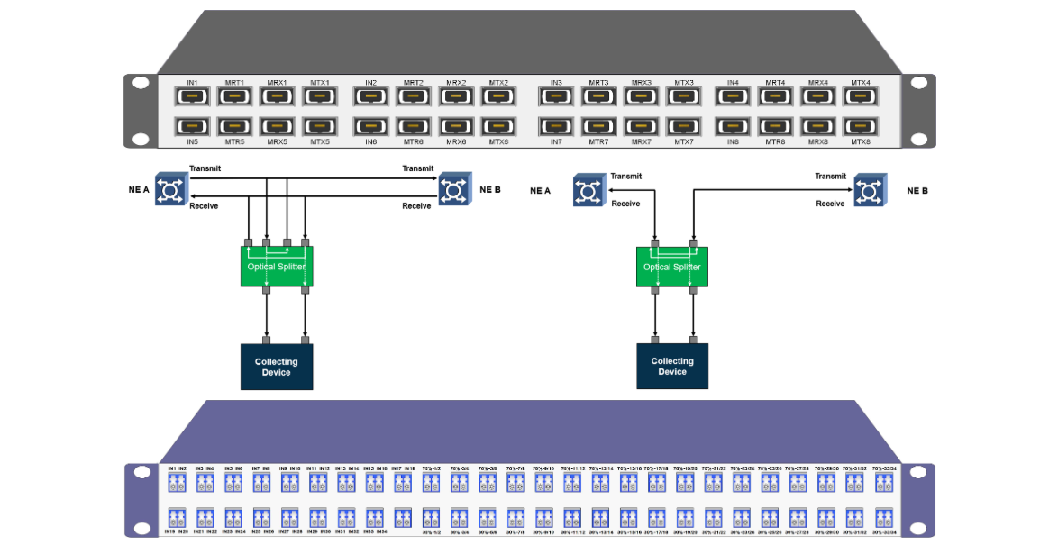
5.5 Flexible Split-Ratio Customization Aligned with Unique Monitoring Bandwidth Requirements
Per official Mylinking product documentation, configurable split ratios include standard industry specifications (70:30,80:20,90:10) alongside fully bespoke non-uniform split customization upon client project request:
○ High-monitoring-bandwidth scenarios (full 10G packet capture via high-resolution network forensics): select 70/30 split (30% optical signal allocated to MON port monitoring output)
○ Low-loss priority core backbone links (minimize primary production path insertion loss): deploy 90/10 split (only 10% signal diverted for monitoring to preserve maximum optical power along primary inline transmission path) Mylinking
This flexible split tuning capability makes Mylinking Passive Network Tap adaptable to disparate use cases ranging from core data center backbone tapping down to low-bandwidth access-layer fiber trunk monitoring.
6. Detailed Product Specification & Customization Options of Mylinking Passive Tap FBT Optical Splitter
Sourced directly from Mylinking’s official FBT Passive Tap product landing page technical datasheet content, below structured specification breakdown improves SEO relevance for long-tail search queries like “FBT fiber passive tap specifications”, “custom split ratio passive network tap”:
6.1 Core Optical Performance Specifications
| Optical Parameter | Standard Mylinking FBT Passive Tap Rated Value |
| Operating Wavelength Range | 1260nm ~ 1650nm (full C+L+S telecom band coverage) |
| Typical Insertion Loss (Primary Network Path) | ≤0.8dB (varies per pre-defined split ratio) |
| Polarization Dependent Loss (PDL) | ≤0.1dB |
| Directivity | ≥55dB |
| Operating Temperature | -40°C ~ +85°C (industrial wide-temperature rating) |
| Storage Temperature | -55°C ~ +125°C |
6.2 Mechanical & Form-Factor Customization Options
(1) Rack Mount Chassis Form: Standard 19-inch 1U/2U rack-mount metal chassis (as shown on official product hardware images), customizable compact standalone plastic packaging for field cabinet/outside plant (OSP) deployments Mylinking.
(2) Fiber Core Compatibility: Single-mode 9/125μm / Multimode 50/125μm /62.5/125μm fiber configurable per client cabling standard.
(3) Connector Types: LC/UPC, SC/UPC, FC/UPC, ST/UPC as default termination; APC polish connector customization available for high-precision low-reflection backbone deployments.
(4) Split Ratio Configuration: In-stock pre-assembled 70:30/80:20/90:10 split variants; custom arbitrary split ratios from 5/95 up to 45/55 via factory pre-production order.
6.3 Scalable Port Density Modular Design
Mylinking’s rack-mount passive tap chassis utilizes modular port bank construction matching the reference inline topology diagram’s multi-tap-module layout: users can populate 2-port independent inline tap modules incrementally within a single chassis (2/4/8/16 total inline tap ports per rack unit), enabling pay-as-you-grow network monitoring expansion without purchasing redundant empty chassis hardware—an economical advantage highlighted prominently for cost-focused enterprise procurement SEO targeting.
7. Vertical Industry Use Cases of Inline Passive Fiber Tap for Network Traffic Capture & Enterprise Network Security Enhancement
Industry-specific application subsections capture high-intent vertical SEO keywords (e.g., “banking network security monitoring”, “healthcare HIPAA network traffic capture”) while contextualizing real-world ROI of Mylinking Passive Network Tap across five highest-demand market segments:
7.1 Financial Services & Banking Compliance Monitoring
Global retail/investment banks face strict PCI DSS, SOX, and local financial regulatory mandates requiring continuous full-traffic logging of all customer transaction perimeter links and inter-bank core fiber trunks. Inline Mylinking passive taps deployed between core firewall and data center access switches enable lossless Network Traffic Capture of every card payment transaction, user online banking session, and inter-bank fund transfer flow. Full archived packet data satisfies regulatory audit trail requirements while enabling instant breach forensics upon suspected fraudulent data exfiltration; zero-attack-surface passive design satisfies banking industry’s stringent network perimeter security hardening standards to avoid regulatory penalties from incomplete traffic visibility gaps.
7.2 Enterprise Data Center NOC Performance & Fault Troubleshooting
Mid-to-large enterprise IT NOC teams leverage inline Passive Network Tap deployment across core router-firewall and inter-data-center fiber trunks to feed complete replicated traffic into network performance monitoring (NPM) and packet analysis platforms. Full unfiltered captured packet data accelerates root-cause analysis of intermittent network latency spikes, unexplained application downtime, and hidden TCP retransmission bottlenecks that remain undetectable via limited SPAN mirror visibility, cutting average troubleshooting resolution time by upwards of 60% for enterprise IT departments—core value proposition for organic SEO targeting “data center network monitoring solutions”.
7.3 Government & Defense High-Security Network Traffic Audit
Federal government and defense classified networks mandate air-gapped separation between production classified LAN and external security analysis infrastructure to prevent classified data leakage and APT infiltration. Mylinking passive fiber taps’ inherent one-way optical split design delivers required physical isolation: replicated audit traffic is safely routed to standalone offline forensic analysis workstations without any possible reverse signal injection back into secure classified production network, satisfying DoD and federal information security compliance rules for continuous network audit and threat monitoring via full Network Traffic Capture.
7.4 ISP & Telecommunication Backbone Fiber Link Monitoring
Tier-2/3 internet service providers deploy rack-mounted Mylinking multi-port passive tap chassis across core POP site upstream fiber trunks linking border routers and aggregation switches. Captured full-rate traffic feeds into DPI (Deep Packet Inspection) appliances for user bandwidth profiling, illegal traffic filtering, and inter-carrier peering traffic reconciliation, eliminating costly packet loss issues previously encountered with legacy SPAN-based trunk monitoring on high-capacity 10G/100G fiber backbone links.
7.5 Healthcare Regulated Network HIPAA Compliance Traffic Logging
HIPAA regulatory rules oblige US healthcare providers to log all PHI (Protected Health Information) data transmission across hospital core network links to prevent unauthorized patient record exfiltration. Inline passive taps installed at core firewall-hospital access switch interconnection points deliver complete bidirectional PHI-bearing traffic capture for long-term encrypted archive storage, enabling auditable traceability of every internal/external patient data transfer while passive tap’s non-exploitable hardware design blocks threat actors from tampering with monitoring infrastructure to hide unauthorized data theft activity.
8. Step-by-Step Best Practices for Inline Passive Fiber Tap Installation & Long-Term Network Monitoring Optimization
Optimized for Google “passive fiber tap installation best practices” long-tail SEO traffic, below standardized deployment workflow aligns directly with the official inline solution schematic architecture:
(1) Pre-Deployment Site Assessment: Map target inline fiber trunk (Firewall → Access Switch per reference topology), confirm fiber core type (SM/MM), operating wavelength, and required split ratio (select 70/30 for high-volume capture,90/10 for ultra-low primary insertion loss priority links); pre-order matching connector-terminated Mylinking passive tap hardware per on-site cabling standard.
(2) Rack Mount Physical Installation: Secure Mylinking rack-mount tap chassis into vacant standard 19-inch server rack U-space near target fiber run to minimize excess patch cord length and signal attenuation loss.
(3) Hot Inline Fiber Termination: Carefully disconnect existing continuous fiber patch cord bridging Firewall output and Switch uplink; terminate Firewall-side fiber end into Tap NETWORK A port, Switch-side fiber end into Tap NETWORK B port to complete inline production path continuity—live network remains fully operational throughout physical wiring modification thanks to passive transparent signal pass-through design.
(4) Monitoring Output Cabling: Run dedicated orange monitoring fiber from Tap MON A/MON B ports toward designated Network Analysis Tool/IDS/NDR appliance input interfaces following the reference diagram’s orange monitoring cabling routing standard, completing isolated off-band capture feed without touching production network routing configuration.
(5) Post-Install Validation Testing: Verify primary network end-to-end connectivity via ping/bandwidth throughput testing between firewall and downstream end-user workstations; validate full bidirectional packet replication by checking captured traffic visibility within analysis tool software to confirm both inbound/outbound flows populate correctly.
(6) Long-Term Preventative Maintenance: Annual fiber connector cleaning inspection only required; passive tap hardware requires zero firmware updates, power maintenance, or configuration changes for multi-decade continuous operation—core TCO advantage for ongoing network monitoring infrastructure management.
9. Frequently Asked Questions About Passive Network Tap Deployment & Network Traffic Capture Optimization
FAQ section targets high-volume Google People Also Ask search queries around core SEO keywords to boost organic ranking visibility:
Q1: Does inline Passive Network Tap introduce latency or packet loss into live production fiber traffic?
A: Mylinking FBT Passive Tap is a purely passive optical component with no electrical signal processing; primary production path suffers only fixed minimal calibrated insertion loss (<0.8dB typical), zero packet truncation, zero forwarding latency added to live traffic flows—all signal modification is isolated exclusively to split-off MON port replicated monitoring traffic.
Q2: Can passive fiber taps be installed on live active fiber without taking the monitored link offline?
A: Yes, inline hot-cut installation is the standard Mylinking Passive Tap deployment method; as validated in thousands of global enterprise field deployments, proper sequential fiber termination into NETWORK A/B ports preserves continuous live circuit connectivity with zero planned downtime required.
Q3: What split ratio should I select for my enterprise’s core firewall perimeter link network monitoring?
A: Standard recommendation: 70:30 split for core perimeter firewall links requiring full-rate comprehensive Network Traffic Capture for cybersecurity threat hunting; deploy 90:10 split for ultra-long-haul single-mode backbone fiber where minimizing primary path optical attenuation is prioritized over maximum monitoring bandwidth availability. Mylinking engineering team provides free custom split ratio sizing consultation for complex mixed-bandwidth multi-link projects.
Q4: Is passive tap monitoring traffic one-way only? Can attackers send data back into production via tap monitor ports?
A: Physically impossible for reverse signal injection: FBT split core’s evanescent coupling mechanism only bleeds optical power from primary NETWORK ports toward MON outputs; light cannot travel backward from monitoring ports into inline production fiber, forming permanent optical air-gap security isolation to protect core network infrastructure from compromised analysis tool exploits.
10. Final Conclusion: Why Mylinking Inline Passive Fiber Tap Is Your Preferred Long-Term Network Security Monitoring Infrastructure Investment
Against increasingly sophisticated global cyber threats and tightening worldwide data protection compliance legislation, complete, lossless, secure full-spectrum Network Traffic Capture via inline Passive Network Tap has evolved from optional IT enhancement to mandatory foundational infrastructure for resilient modern Network Security and proactive end-to-end Network Monitoring. Mylinking’s purpose-built FBT Optical Splitter passive tap product portfolio, validated via the proven inline deployment topology featured in this article’s reference solution diagram, resolves every core pain point of legacy SPAN mirror and active tapping limitations: eliminating capture packet loss, removing unnecessary production network performance overhead, hardening network perimeter attack surfaces via passive zero-electronics construction, and cutting long-term monitoring infrastructure maintenance costs for global enterprise, government, finance, and telecom end-users.
From small business core firewall perimeter single-link tapping up to hyperscale data center multi-trunk consolidated rack-mounted passive tap deployments, customizable split ratios, universal fiber/wavelength compatibility, and rugged industrial-grade hardware construction solidify Mylinking Passive Network Tap as a cost-effective future-proof investment for organizations prioritizing uncompromised network visibility and robust cybersecurity defense. IT and cybersecurity teams aiming to upgrade incomplete existing monitoring infrastructure or design greenfield full-visibility network observability architecture are encouraged to access Mylinking’s official product page (https://www.mylinking.com/mylinking-passive-tap-fbt-optical-splitter-product/) to download detailed technical datasheets, request custom project quotation, and coordinate free pre-sales engineering deployment consultation tailored to unique organizational network monitoring requirements.
Post time: Jun-03-2026


